Power factor calculator. Active, apparent and reactive power. Cosine of phi.
Calculator
| Unknown parameter |
Parameter | ||
|---|---|---|---|
| Active power (P) | W | ||
| Apparent power (S) | VA | ||
| Power factor | |||
| phi (φ) (*) | deg | ||
| Reactive power (Q) (*) | VAR |
(*) The calculation of φ and reactive power is only correct for linear loads. See clarifications below
Clarifications on power factor
Active power (P)
It is the value of the useful power, that is, the electrical power that can be transformed into work.Reactive power (Q)
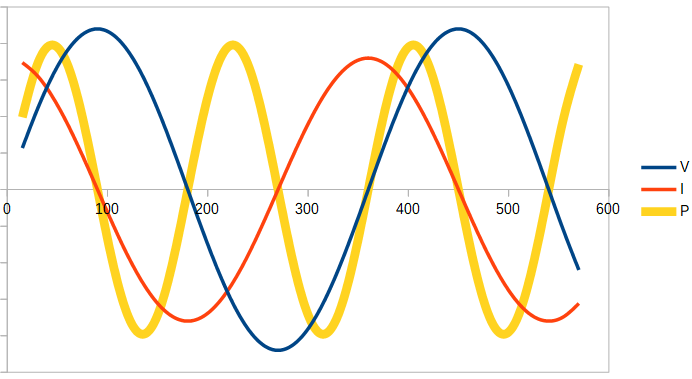
It is not a power actually consumed in the installation, it does not produce useful work. It appears when there are inductive or capacitive loads and is necessary to generate magnetic and electric fields. It is measured in volt-amperes reactive (VAR). Electric companies may penalize if the value of this reactive power is too high. One way to understand this, is to think of reactive power as flowing sometimes in one direction and sometimes in the opposite direction and, averaged over time, its total value is value is zero. To see this more clearly, let's think of a load fed by a sine wave whose voltage and current are 90º out of phase (I anticipate that this means that all the power is totally reactive). Being 90º out of phase, during two quarters of each cycle the product of the voltage by the current is positive (remember that P = V·I) and in other two cycles is negative (this would correspond to the second graph below, where it is observed that the power is a sine wave whose average value is zero). That is, there is no net energy transfer to the load. It is for this reason that reactive power is often considered undesirable, It is not capable of transferring energy and yet it must be taken into account for the sizing of the installation (cables, transformers, etc.). In addition, installations never behave ideally, for example cables always have a certain electrical resistance, so this reactive power will result in a loss of energy. Let us see in more detail what it means that reactive power does not transmit useful work. If the voltage and current are in phase, the power is always positive at all times, regardless of whether the voltage and current are positive or negative: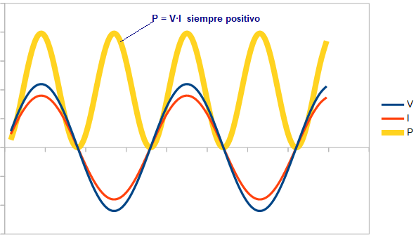
If the load is fully reactive, the power will oscillate between negative and positive values, averaging zero over time.
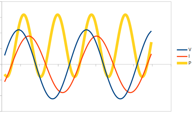
Finally, if the load is partially reactive, the power value will sometimes be positive and sometimes negative, but its average over time will not time will not cancel (it will be positive or negative depending on whether the load is capacitive or inductive, i.e. depending on the direction in which the current is out of phase with respect to the voltage):
The calculator shows the value of the reactive power but does not clarify its sign, as this depends on the type of load. If we have a capacitive load, where the current is ahead of the voltage, the sign of the reactive power must be negative. On the other hand, we have a positive reactive power if the load is inductive, in which case the current lags behind the voltage.
Apparent power
It is measured in volt amperes (VA), or its multiple kVA (1kVA = 1000 VA). In the case of sinusoidal (sine) waves, it is the vector sum of the active power and the reactive power:.
- S2 = P2 + Q2
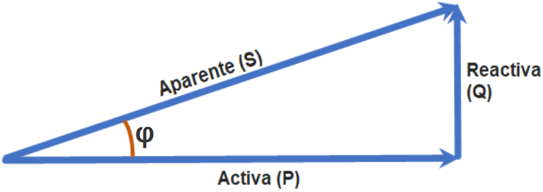
Where φ (phi) is the angle of phase difference between V and I. From this we can also conclude that the active power, P, in W, is equal to the apparent power, S, in VA multiplied by the cosine of phi (cosφ). power, S, in VA multiplied by the cosine of phi (cosφ):
- P = S · cosφ
Power factor
It is defined as:- Power Factor = P / S
It is a dimensionless number obtained by dividing the active power by the apparent power. A value equal to unity indicates that the voltage and current are in phase and, therefore, there is no reactive power. phase and therefore there is no reactive power. Its maximum value is one and the closer it is to unity the more work can be produced for a given voltage and current.
Angle phi (φ)
It is the angle of phase difference between voltage and current. It is also the angle between apparent and active power when the loads are linear, according to the vector diagram above.Case of non-linear loads. Harmonics
In the case of linear loads it is true that: Power factor = cosφ, however, in general this equality is not correct, or at least not exact. When we have non-linear loads, the current is no longer pure sinusoidal and for the calculation of the apparent power we have to calculate independently the values for each of these harmonics. For the same reason, the calculation of φ made by our calculator above is only correct when we have sine waves. The power factor is still equal to P/S, but in the apparent power (S), the harmonic components are also included.La potencia aparente vendrĂa dada por la ecuaciĂłn:
- S2 = P2 + Q2 + D2
where D is the harmonic distortion component.